Technical Support & Inquiry >>
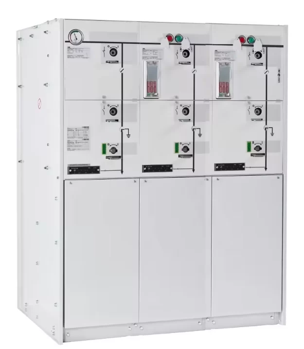
Ring Main Unit (RMU) — Medium Voltage Distribution Switchgear (12–36kV)
IEC-Standard RMU Solutions
We supply IEC-standard RMU solutions with flexible configurations (C-C-F / V-V-F / metering / protection) and project-based options for motorization and SCADA interfaces.
1. What is an RMU?
A Ring Main Unit (RMU) is a compact medium-voltage switchgear assembly designed for distribution networks. It enables safe sectionalizing, protection, and metering in ring networks, radial feeders, substations, and compact transformer stations, helping reduce footprint, simplify installation, and improve network reliability.
2. Typical Applications
Utility Distribution Networks (Ring / Radial Feeders)
Used for feeder sectionalizing and transformer protection in urban and suburban distribution networks. RMUs are commonly installed at compact substations and public distribution points to improve reliability and shorten outage restoration time.
Industrial & Commercial Substations
Applied in factories, industrial parks, data centers, and commercial loads for MV distribution and internal substation switching. Optional metering and protection interfaces support local monitoring and maintenance requirements.
Renewable Energy & Grid-Connection Projects
Used in PV/wind step-up stations and hybrid microgrids for MV switching and protection coordination. RMUs can be configured for project-specific interfaces to protection & metering panels and SCADA/RTU systems (optional).
3. Quick Specs (Typical Range)
| Item | Typical Range / Options |
|---|---|
| Rated voltage (Um) | 12 kV / 24 kV / 36 kV (project-based) |
| Rated current | 630 A / 1250 A (project-based) |
| Short-circuit withstand | 20 kA / 25 kA (project-based) |
| Insulation medium | SF₆ gas insulated / Solid insulated (depending on model) |
| Functional units | Load break switch unit / Circuit breaker unit / Fuse switch unit / Metering unit |
| Typical configurations | C-C-F, V-V-F, C-C-V, metering + feeder options |
| Operation | Manual / Motorized (optional) |
| Protection interface | For feeder/transformer protection IED & metering (optional) |
| Enclosure / environment | Indoor / outdoor options (project-based) |
4. Common Functional Units
Available depending on configuration:
- Load Break Switch (LBS) Unit – feeder switching and sectionalizing
- Circuit Breaker Unit – feeder protection switching (project-based)
- Fuse Switch Unit – transformer protection, commonly used for distribution transformer feeders
- Metering Unit – CT/VT metering compartment (project-based)
- Cable Compartments – standard MV cable termination interfaces (project-based)
5. Typical Network Applications
- Transformer feeder protection (RMU + fuse / breaker)
- Ring network sectionalizing (two LBS + protection unit)
- Industrial MV distribution (feeder breaker + metering + protection IED interface)
6. Standards
RMU solutions are supplied primarily for IEC-based markets. Compliance support can be provided based on project requirements and test scope.
- IEC medium-voltage switchgear standards (e.g., IEC 62271 series)
- Project-based deliverables: routine test records, type test references, third-party inspection (upon request)
Notes for US Projects
For US projects, ANSI/IEEE alignment and third-party certification/testing (e.g., NRTL/UL route) can be evaluated on a project basis, subject to project specification and scope.
7. Routine Tests & Factory QA
Before shipment, each RMU can be supplied with routine test documentation (depending on contract scope), such as:
- Mechanical operation checks
- Interlock verification
- Insulation / dielectric checks (as applicable)
- Gas pressure/leak checks (for SF₆ models, as applicable)
- Functional verification of auxiliary circuits (if provided)
Type Test / Third-Party Witness (Optional)
Type test references and third-party witness inspection can be arranged upon request, subject to model and project scope.
8. Scope of Supply
Typical scope of supply (project-based):
- RMU assembly with specified functional units
- Operation mechanism (manual / motorized if applicable)
- Cable compartments and termination interface per project requirement
- Nameplate, wiring diagrams (if auxiliary circuits are included)
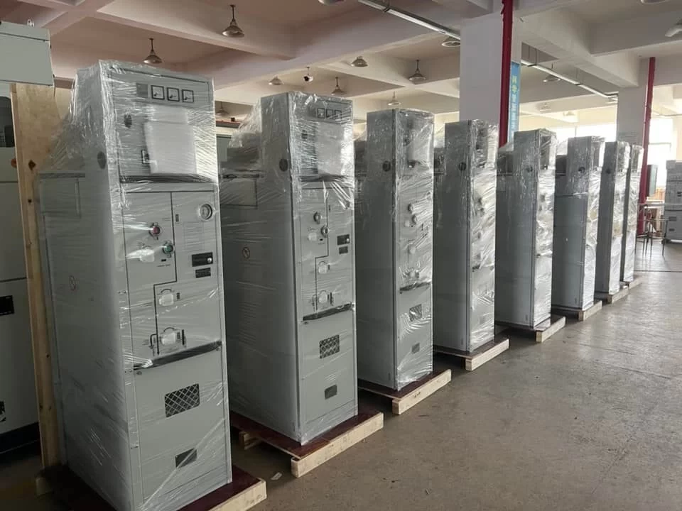
- Packing suitable for sea shipment
- Routine test report package (per contract)
Optional items
- CT/VT metering compartment
- Protection & metering interface design to panel (project-based)
- Spare parts kit (recommended for first orders)
- Additional accessories required by utility specification
9. RMU RFQ Checklist
A. Network & Rating
- Rated voltage (kV) and frequency (50/60 Hz)
- Rated current (A)
- Short-circuit level (kA) and duration (e.g., 1s / 3s)
- System earthing method (solid / resistance / isolated, if specified)
B. Configuration
- Required configuration (e.g., C-C-F / V-V-F / C-C-V)
- Functional unit types (LBS / CB / fuse switch / metering)
- Number of cable ways and cable termination type
C. Installation & Environment
- Indoor or outdoor installation
- Ambient temperature range / altitude / IP requirement (if specified)
- Preferred operation: manual or motorized; remote control required? (Y/N)
D. Interfaces & Documentation
- Auxiliary power supply for motorization (if any)
- Required interface to protection / metering / SCADA (if any)
- Required standards / specification (IEC / utility spec / project spec)
- Documentation: drawings, routine tests, third-party inspection required? (Y/N)
10. Downloads
Available upon request / under preparation:
- RMU datasheet (PDF)
- GA drawing example (PDF)
- Routine test report sample (PDF)
- RMU RFQ Checklist (PDF)
11. Need a Configuration Recommendation?
Send us your single-line diagram (SLD) or the RFQ checklist, and we will propose a suitable RMU configuration and quotation.
MV Switchgear (AIS) — Air-Insulated Medium Voltage Switchgear (3.6–40.5kV)
Designed for indoor switchrooms and engineered outdoor enclosures (project-based).
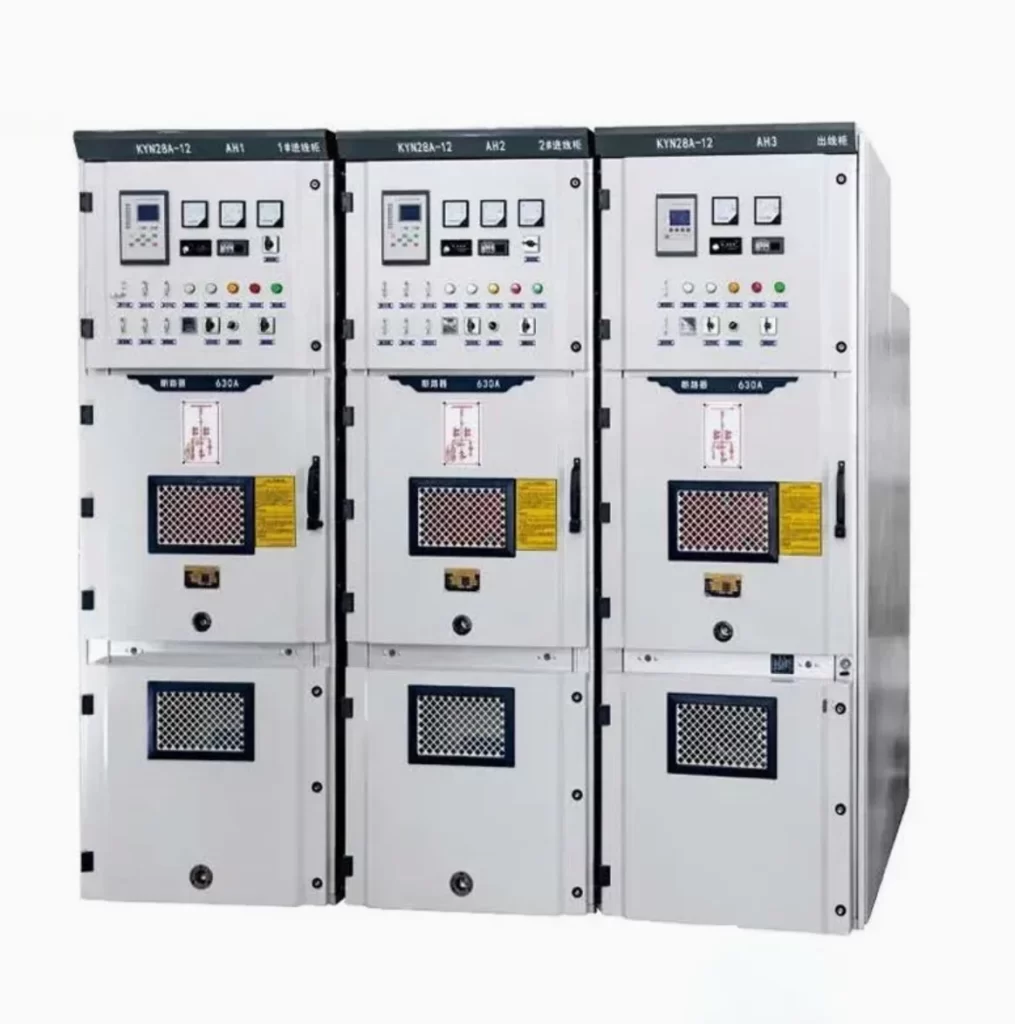
1. What is MV AIS Switchgear?
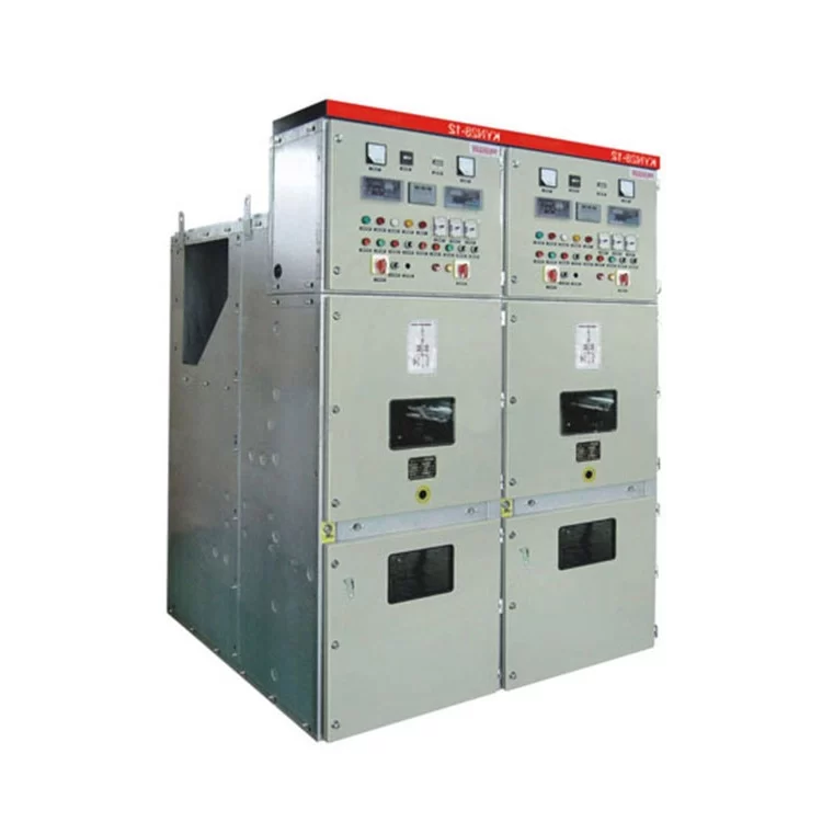
Air-insulated switchgear (AIS) is a medium-voltage switchgear system where primary insulation to earth is provided by air, with solid insulation used on key components. Compared with RMU, AIS typically offers more flexible panel arrangements, easier maintenance access, and higher customization for substation layouts.
2. Typical Applications
Utility Distribution Substations & Feeder Bays
Used in distribution substations as incoming/outgoing feeder panels, bus sectionalizing, and metering bays. AIS supports standardized bay design, clear operation interlocking, and easier expansion.
Industrial Substations & Critical Infrastructure
Commonly installed in industrial parks, factories, mining and processing plants, and data centers where panel-by-panel layout and maintainability are key. Options for higher enclosure protection and enhanced safety features can be evaluated per project.
Renewable Step-up and Collector Substations
Applied in PV and wind collector substations for feeder switching, protection coordination, and metering. AIS panels can be configured for project-specific protection and control requirements (optional).
3. Quick Specs (Typical Range)
The following ranges are project-based and can be confirmed by configuration and test scope.
| Item | Typical Range / Options |
|---|---|
| Rated voltage (Um) | 3.6 / 7.2 / 12 / 24 / 36 / 40.5 kV (project-based) |
| Rated current | 630 A / 1250 A / 2000 A / 2500 A / 3150 A (project-based) |
| Short-circuit withstand | 16–40 kA (project-based) |
| Circuit breaker type | Vacuum circuit breaker (VCB), withdrawable or fixed (project-based) |
| Panel types | Incomer / outgoing feeder / bus coupler / metering / transformer feeder / capacitor bank (project-based) |
| Busbar | Single bus / double bus / sectionalized (project-based) |
| Insulation level | Power frequency withstand / lightning impulse (BIL) (project-based) |
| Internal arc | Internal arc classification available on request (project-based) |
| Enclosure | Indoor switchroom; outdoor enclosure option (project-based) |
4. Typical Panel Line-up (Example)
AIS switchgear is usually supplied as a lineup of functional panels (bays). Typical lineups include:
- Incomer panel (VCB)
- Outgoing feeder panels (VCB/LBS depending on design)
- Bus coupler / bus sectionalizer
- Metering panel (CT/VT)
- Transformer feeder panel
- Capacitor bank panel (if reactive compensation is included)
If you share your SLD (single-line diagram) or bay list, we can propose a complete lineup and technical offer.
5. Standards
AIS switchgear is supplied primarily for IEC-based markets. Compliance support can be provided based on project requirements and test scope.
- IEC medium-voltage switchgear standards (e.g., IEC 62271 series)
- Project-based deliverables: routine test records, type test references, third-party inspection (upon request)
Notes for US Projects
For US projects, ANSI/IEEE alignment and third-party certification/testing (e.g., NRTL/UL route) can be evaluated on a project basis, subject to project specification and scope.
6. Routine Tests & Factory QA
Before shipment, AIS switchgear can be supplied with routine test documentation (depending on contract scope), such as:
- Mechanical operation checks (including racking tests for withdrawable VCB)
- Interlock verification
- Dielectric / insulation checks (as applicable)
- Secondary wiring functional verification (if provided)
- Breaker timing / contact resistance checks (project-based)
Type Test / Third-Party Witness (Optional)
Type test references and third-party witness inspection can be arranged upon request, subject to model and project scope.
7. Scope of Supply
Typical scope of supply (project-based):
- AIS switchgear panels/lineup with specified bay arrangement
- VCB (withdrawable/fixed as specified)
- Busbar system and standard interlocks
- CT/VT compartment (if applicable)
- Nameplate, wiring diagrams (if auxiliary circuits are included)
- Packing suitable for sea shipment
- Routine test report package (per contract)
Optional items
- Protection & control panels / relays (project-based)
- Metering & power quality meters (project-based)
- SCADA/RTU interface wiring (optional)
- Spare parts kit (recommended for first orders)
- Outdoor enclosure / higher IP options (project-based)
8. MV Switchgear RFQ Checklist
A. Network & Rating
- Rated voltage (kV) and frequency (50/60 Hz)
- Rated current (A) and short-circuit level (kA, duration 1s/3s)
- Neutral earthing method (solid/resistance/isolated)
- Required insulation level / BIL (if specified)
B. Line-up & Panels
- Single-line diagram (SLD) or bay list (incomer/outgoing/bus coupler/metering/capacitor)
- Busbar scheme (single/double/sectionalized)
- Breaker type (withdrawable or fixed) and number of panels
- Cable entry (bottom/top), number of cores, termination type
C. Instruments & Secondary
- CT/VT requirements (ratio, class, burden)
- Protection relay requirement (brand/spec or TBD)
- Metering/power quality meter requirement (if any)
D. Installation & Environment
- Indoor switchroom or outdoor enclosure requirement
- Ambient temperature/altitude, IP requirement, anti-condensation/heater requirement (if any)
- Internal arc requirement (if any)
E. Documentation & Inspection
- Drawings needed (GA, schematic, wiring)
- Routine tests / third-party inspection / FAT witness required? (Y/N)
Gas-insulated Switchgear (GIS) — Compact MV Switchgear for Space-Constrained Substations (12–40.5kV)
MV GIS Switchgear Solutions
Project-based supply for utility, industrial, and renewable collector substations where space, contamination, or environmental conditions require sealed insulation.
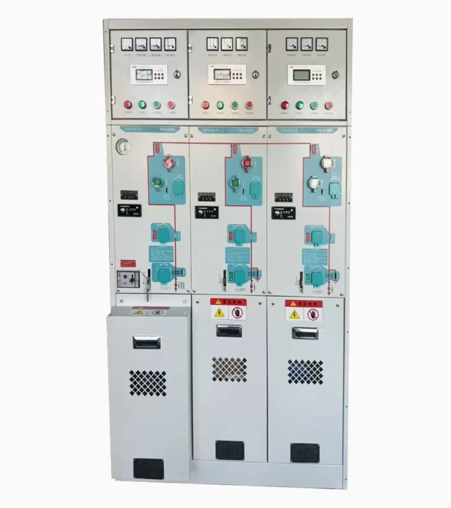
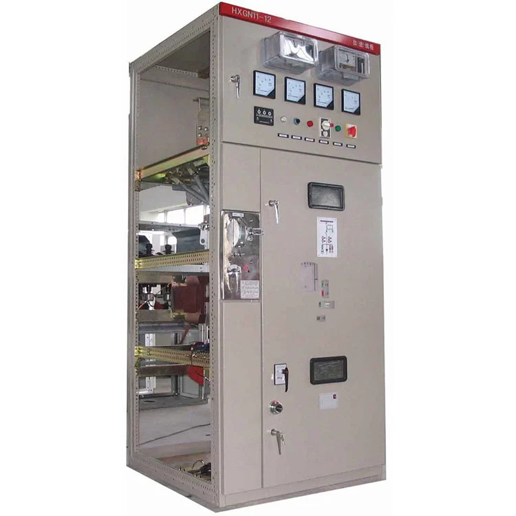
1. What is GIS?
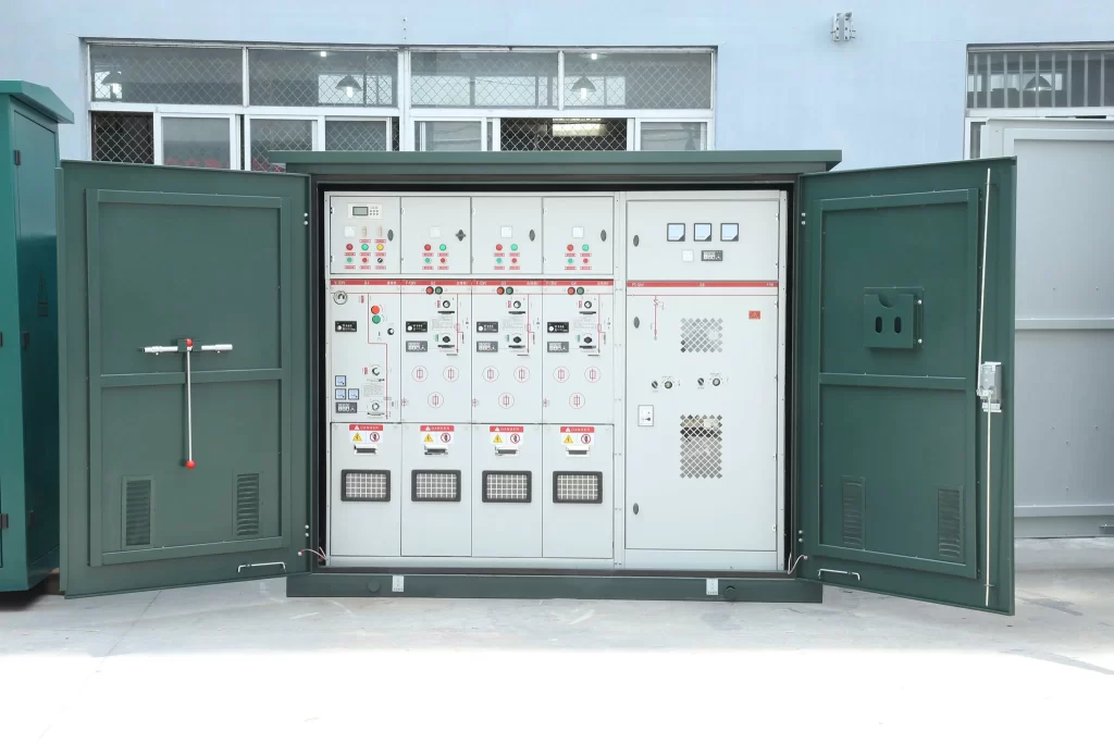
Gas-insulated switchgear (GIS) is medium-voltage switchgear where live parts are enclosed in a sealed metal housing and insulated by a gas medium, commonly SF₆ or gas-mixture depending on design. Compared with AIS, GIS typically offers a smaller footprint, higher environmental resistance (dust, humidity, salt fog), and reduced maintenance exposure in harsh conditions.
2. Typical Applications
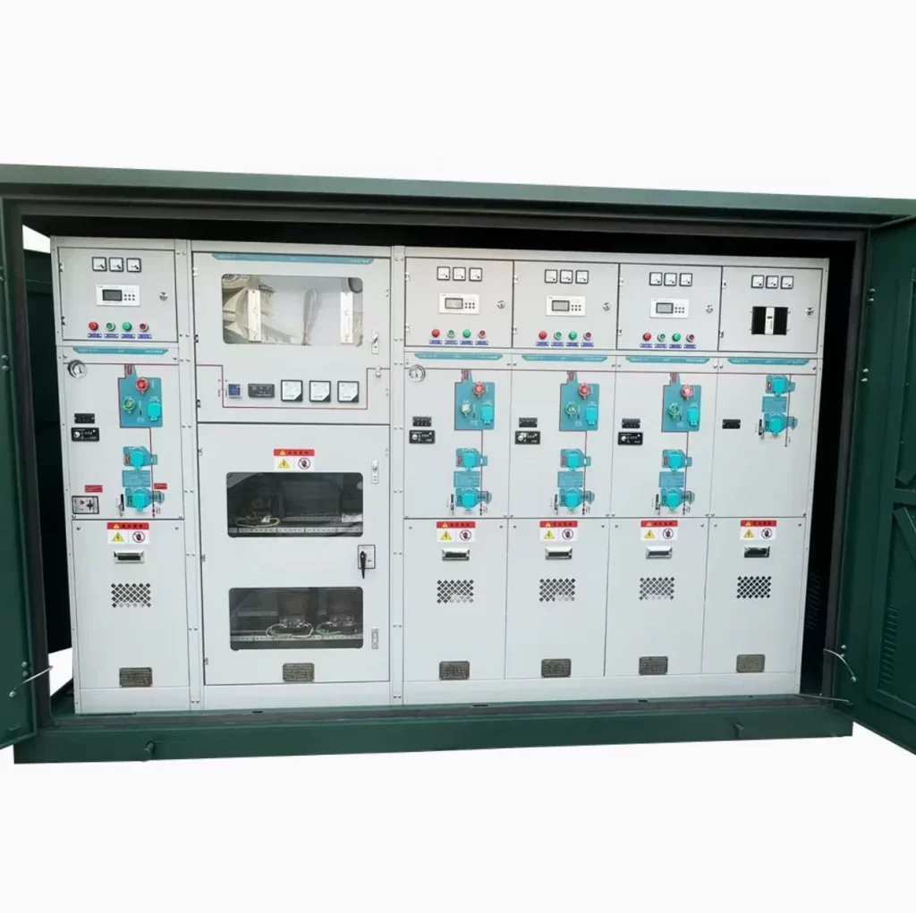
Urban Substations & Indoor Switchrooms with Limited Space
GIS is often selected where building footprint is constrained and a compact, sealed switchgear lineup is preferred, supporting reliable MV distribution in dense urban installations.
Coastal / High-Humidity / Dusty Environments
Sealed insulation helps reduce the impact of external contamination such as salt fog, humidity, industrial pollution, and dust, improving operational stability in challenging climates.
Renewable Collector Substations & Critical Loads
Applied in PV and wind collector substations and critical infrastructure sites where availability and environmental robustness are prioritized. Project-based protection and metering interfaces, as well as remote operation options, can be evaluated.
3. Quick Specs (Typical Range)
Typical ranges are project-based and confirmed by configuration and test scope.
| Item | Typical Range / Options |
|---|---|
| Rated voltage (Um) | 12 / 24 / 36 / 40.5 kV (project-based) |
| Rated current | 630 A / 1250 A / 2000 A (project-based) |
| Short-circuit withstand | 16–31.5 kA (project-based) |
| Insulation medium | SF₆ / gas-insulated design (depending on model) |
| Switching units | Load break switch (LBS) / Vacuum circuit breaker (VCB) / fuse-switch unit (project-based) |
| Typical modules | Incomer / outgoing feeder / bus coupler / metering / transformer feeder (project-based) |
| Operation | Manual / motorized (optional) |
| Monitoring | Gas pressure monitoring & interlocks (as applicable) |
| Installation | Indoor; outdoor enclosure option (project-based) |
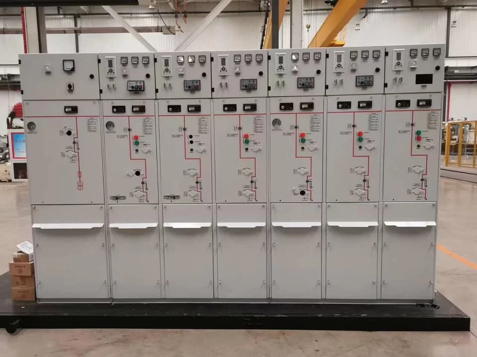
4. Typical Functional Modules (Example)
GIS is typically configured as a lineup of modular bays. Common modules include:
- Incomer module (VCB)
- Outgoing feeder modules (LBS/VCB depending on protection philosophy)
- Bus coupler / sectionalizer module
- Metering module (CT/VT compartment, project-based)
- Transformer feeder module (fuse-switch or VCB option, project-based)
If you provide your SLD (single-line diagram) and bay list, we can propose a suitable GIS lineup and quotation.
5. Standards
GIS solutions are supplied primarily for IEC-based markets. Compliance support can be provided based on project requirements and test scope.
- IEC medium-voltage switchgear standards (e.g., IEC 62271 series)
- Project-based deliverables: routine test records, type test references, third-party inspection (upon request)
Notes for US Projects
For US projects, ANSI/IEEE alignment and third-party certification/testing (e.g., NRTL/UL route) can be evaluated on a project basis, subject to project specification and scope.
6. Routine Tests & Factory QA
Before shipment, GIS switchgear can be supplied with routine test documentation (depending on contract scope), such as:
- Mechanical operation checks & interlock verification
- Dielectric / insulation checks (as applicable)
- Gas filling / pressure checks and leak verification (as applicable)
- Secondary wiring functional verification (if provided)
- Breaker timing / contact resistance checks (project-based)
Type Test / Third-Party Witness (Optional)
Type test references and third-party witness inspection can be arranged upon request, subject to model and project scope.
7. Scope of Supply
Typical scope of supply (project-based):
- GIS lineup with specified bay arrangement (modules)
- Switching units (LBS / VCB / fuse-switch as specified)
- Sealed gas compartments and monitoring devices (as applicable)
- Standard interlocks and indicators
- Nameplate, wiring diagrams (if auxiliary circuits are included)
- Packing suitable for sea shipment
- Routine test report package (per contract)
Optional items
- CT/VT metering compartment (project-based)
- Protection & control panels / relays (project-based)
- SCADA/RTU interface wiring (optional)
- Spare parts kit (recommended for first orders)
- Outdoor enclosure / enhanced corrosion protection (project-based)
8. GIS RFQ Checklist
A. Network & Rating
- Rated voltage (kV) and frequency (50/60 Hz)
- Rated current (A) and short-circuit level (kA, duration 1s/3s)
- Neutral earthing method (solid / resistance / isolated)
- Environmental conditions (coastal / humidity / dust / altitude / temperature)
B. Line-up & Modules
- Single-line diagram (SLD) or bay list (incomer / outgoing / bus coupler / metering / transformer feeder)
- Required switching philosophy (LBS vs VCB; fuse-switch option)
- Cable entry (bottom / top), termination interface requirements
C. Operation & Interfaces
- Motorization / remote control required? (Y/N)
- Required interface to protection / metering / SCADA (if any)
- Gas monitoring requirements / alarms interface (if specified)
D. Documentation & Inspection
- Drawings needed (GA, schematic, wiring)
- Routine tests / third-party inspection / FAT witness required? (Y/N)
- Required standards / specification (IEC / utility spec / project spec)
9. Downloads
Available upon request / under preparation:
- GIS datasheet (PDF)
- GA drawing example (PDF)
- Routine test report sample (PDF)
- GIS RFQ Checklist (PDF)
10. Need a Configuration Recommendation?
Send us your SLD and key requirements (voltage / current / short-circuit / environment). We will propose a suitable GIS lineup and quotation.